Keyboard Matrix
This section covers the basic keyboard identification and physical matrix configuration in your keyboard.toml file.
Matrix Configuration
The [matrix] section defines your keyboard's physical key matrix wiring. This tells RMK which GPIO pins connect to your key switches.
Skip [matrix] section for split keyboards. Use the [split.central/peripheral.matrix] section to define matrix configuration for split central and peripherals.
Understanding Key Matrix
A keyboard matrix uses diodes to enable multiple key detection. Here's how it works:
By default, RMK assumes that your pins are col2row, meaning that the output pins (anodes) represent the columns and the input pins (cathodes) represent the rows. If your schematic shows the opposite, you need to change the configuration to row2col
Standard Matrix Configuration
For keyboards using a traditional diode matrix:
Finding GPIO Pin Names
GPIO pin names vary by microcontroller. Here are the correct formats for each supported chip series:
Examples by Chip Series:
- STM32:
PA0,PB1,PC2, etc. - nRF52:
P0_00,P0_01,P1_15, etc. - RP2040/RP2350:
PIN_0,PIN_1,PIN_28, etc. - ESP32:
GPIO0,GPIO1,GPIO21, etc.
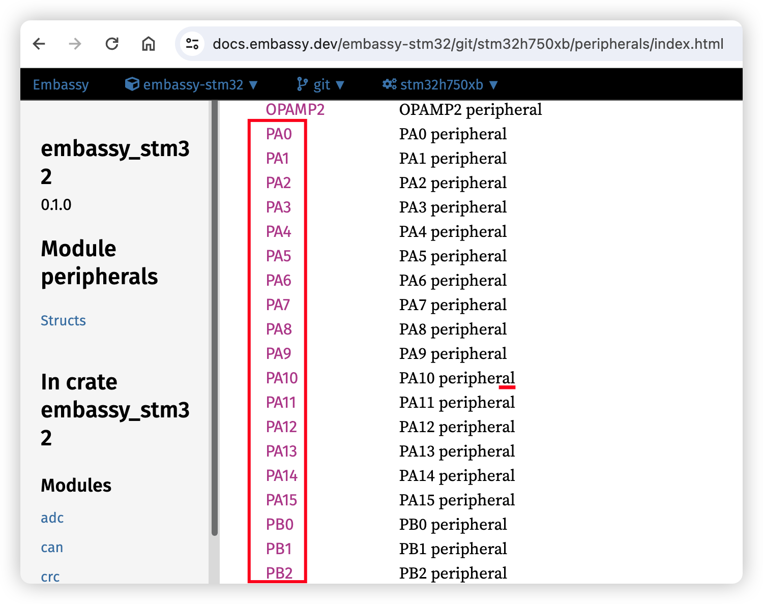
Finding Pin Names:
- Visit Embassy docs
- Navigate to your specific chip (e.g.,
embassy-stm32/stm32h750xb) - Check the peripherals module for valid GPIO pin names:
Matrix Type Configuration
RMK supports two matrix types:
Direct Pin Configuration
For keyboards where each switch connects directly to a GPIO pin (no matrix):
Direct Pin Behavior:
true(default): The pin is pulled high by default, pressing a key pulls it to lowfalse: The pin is pulled low by default, pressing a key pulls it to high- Use
"_"or"trns"for unused positions in the matrix
Debouncer
RMK has two debouncer modes, "default" and "fast":
- The default mode uses a counter-based algorithm that registers a key only after its counter exceeds a certain threshold.
- The fast mode, on the other hand, reacts instantly to a key press and then waits briefly before accepting the next input.
If no debouncer is set, the matrix will default to default mode.
Vial Unlock Keys - [host] Section
For enhanced security, Vial locks certain functions (like matrix testing) by default. You can set a key combination to unlock it. This configuration is part of the [host] section which controls host-side tools and features.
::: tip
- The unlock keys use the physical matrix position (row, column), not the keycode
- Choose keys that are easy to press simultaneously but not commonly pressed together accidentally
- See the Vial Support page for more details on Vial configuration :::
Troubleshooting
Common Issues
Wrong GPIO Pin Names:
- Check embassy documentation for your specific chip
- Ensure pin names match exactly (case-sensitive)
- Verify pins support GPIO functionality
- Use correct format:
P0_00(nRF52),PIN_0(RP2040),PA0(STM32),GPIO0(ESP32) - For nRF52, some pins are behind a feature gate, for example
P0_09/P0_10are used as NFC pins by default. To use it as a normal pin in matrix, you should enable corresponding features(for example, nfc-pins-as-gpio) forembassy-nrfdependency.
Matrix Not Working:
- Verify diode direction in your schematic
- Check if you need
row2col = true, add it to your matrix section if you need
Direct Pins Not Working:
- Verify
matrix_type = "direct_pin"is set - Check
direct_pin_low_activesetting matches your hardware - Ensure unused positions use
"_"or"trns"